devices.esphome.io
Homemaster-MiniPLC
Homemaster-MiniPLC
Device Type: relayElectrical Standard: globalBoard: esp32Difficulty: Comes with ESPhome, 1/5

Product description
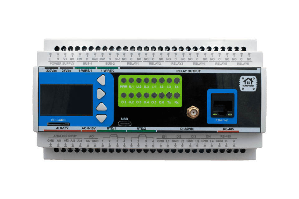
The HOMAMASTER MiniPLC is a powerful and compact automation controller designed for advanced smart home applications. Built around the ESP32-WROOM-32U
Maker: https://www.home-master.eu/
Product page: https://www.home-master.eu/shop/esp32-miniplc-55
Key Features
24V Digital Inputs – 4 industrial-grade inputs for dry contacts.
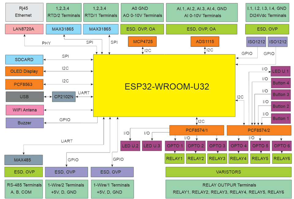
Relay Outputs – 6 relays controlled via I²C expanders for switching AC/DC loads.
Analog Inputs – 4 high-resolution 16-bit channels (ADS1115) for monitoring 0–10V signals.
Analog Output (0–10V) – 1 DAC output (MCP4725) for generating analog control signals.
Temperature Sensors – Supports 2xRTD (MAX31865) sensors.
Two 1-Wire.
User Interface – 4 front-panel buttons and configurable LEDs for local interaction.
OLED Display – 128x64 screen for displaying data and interaction.
RTC with Backup – PCF8563 real-time clock with Home Assistant synchronization.
I²C Expanders – PCF8574 chips expand digital I/O for more flexible device control.
Modbus RTU – UART-based support for extension modules.
Networking
Wi-Fi Connectivity – Integrated Wi-Fi for wireless access and Home Assistant integration.
Ethernet Support – Optional LAN8720 PHY via RMII interface for reliable wired networking.
Pinout

MiniPLC Functional Block Diagram

Programming
The MicroPLC comes with ESPHome pre-installed and can be confgured via:
Improve
Wi-Fi Configuration with Improv
- Power on your HomeMaster MinioPLC.
- Go to 👉 improv-wifi.com.
- Connect via USB (Serial) or Bluetooth LE.
- Enter your Wi-Fi SSID and password, then press Connect.
- The device joins your Wi-Fi and is now ready.
You can then access it via its local address (e.g., http://homemaster-microplc.local) or directly in Home Assistant.
One-Click Import (ESPHome Dashboard Import)
Once connected to Wi-Fi, the MicroPLC will be automatically discovered in ESPHome Dashboard. When the device appears in ESPHome Dashboard, click “Take Control”. The MicroPLC supports dashboard import, automatically pulling its official configuration from GitHub
USB Type-C: Use the ESPHome Dashboard to upload the configuration
- Connect the MicroPLC to your computer with a USB Type-C cable.
- Download the YAML configuration file from our GitHub repository.(https://github.com/isystemsautomation/HOMEMASTER/blob/main/MiniPLC/Firmware/miniplc.yaml)
- Open the ESPHome Dashboard, import the YAML file, and update it with your Wi-Fi SSID and password.
- Flash the device directly from ESPHome Dashboard.
- The MicroPLC supports automatic reset and boot control — there is no need to press reset or boot buttons during programming.
- After flashing, the device will reboot automatically and run the updated firmware.
Bus system configuration
I2C
| PIN | |
|---|---|
| SDA | GPIO32 |
| SCL | GPIO33 |
I2C addresses
| address | |
|---|---|
| pcf8574/2 | 0x38 |
| pcf8574/1 | 0x39 |
| ads1115 | 0x48 |
| SH1106 128x64 | 0x3C |
| pcf8563 | 0x51 |
SPI
| PIN | |
|---|---|
| MISO | GPIO12 |
| MOSI | GPIO13 |
| CLK | GPIO14 |
SPI_CS pins
| PIN | |
|---|---|
| max31865 RTD1 | GPIO01 |
| max31865 RTD1 | GPIO03 |
| SDCARD | GPIO15 |
Basic Config
# ESPHome configuration for MiniPLC# This file configures an ESP32-based automation controller with:# - Modbus RTU over UART# - 1-Wire sensors# - I2C PCF8574 expanders# - I2C PCF8563 RTC# - SPI-based MAX31865 temperature sensors# - ADC inputs via ADS1115# - DAC input MCP4725# - OLED display over I2C# - Ethernet# - Multiple GPIOs managed via PCF8574 expanderssubstitutions: name: "homemaster-miniplc" # Internal device name (used by ESPHome & hostname) friendly_name: "Homemaster MiniPLC" # Friendly name (shown in Home Assistant UI) room: "" # Optional: assign device to a room in HA device_description: "Homemaster MiniPLC" # Description for documentation project_name: "Homemaster.MiniPLC" # Project identifier project_version: "v1.0.0" # Firmware version update_interval: 60s # Default sensor update interval dns_domain: ".local" # mDNS domain suffix for network discovery timezone: "" # Timezone (can be set if device runs in different region) wifi_fast_connect: "false" # If true, reconnects faster (skips Wi-Fi scans) log_level: "DEBUG" # Logging level (NONE, ERROR, WARN, INFO, DEBUG, VERBOSE) ipv6_enable: "false" # Enable IPv6 if supported
esphome: name: "${name}" # Uses substitution for device name friendly_name: "${friendly_name}" # Uses substitution for friendly name comment: "${device_description}" # Metadata comment area: "${room}" # Assign device to a room min_version: 2025.7.0 # Minimum ESPHome version required name_add_mac_suffix: true # Append MAC to hostname to avoid duplicates project: name: "${project_name}" # Project name version: "${project_version}" # Project version
esp32: board: esp32dev # Target board type (generic ESP32 DevKit) framework: type: esp-idf # Use ESP-IDF (official Espressif framework) version: recommended # Recommended stable version
logger: baud_rate: 115200 # Serial logging baud rate level: ${log_level} # Logging level from substitutions
mdns: disabled: false # Enable mDNS for auto-discovery on the network
api: # Enable ESPHome API for Home Assistant integration
ota: - platform: esphome
network: enable_ipv6: ${ipv6_enable}
wifi: ap: {} fast_connect: "${wifi_fast_connect}" domain: "${dns_domain}"
captive_portal: # Captive portal for fallback hotspot
improv_serial: # Allows setup via Improv over Serial
esp32_improv: authorizer: none # No additional authorization required for Improv
dashboard_import: package_import_url: github://isystemsautomation/HOMEMASTER/MiniPLC/Firmware/miniplc.yaml@main import_full_config: true # Allows importing this YAML from GitHub into ESPHome Dashboard
#ethernet:# type: LAN8720# mdc_pin: GPIO23# mdio_pin: GPIO18# clk_mode: GPIO0_OUT# phy_addr: 1
uart: tx_pin: 17 rx_pin: 16 baud_rate: 19200 id: mod_uart
one_wire: - platform: gpio pin: GPIO05 id: hub_1 - platform: gpio pin: GPIO04 id: hub_2
i2c: - id: bus_a sda: 32 scl: 33 frequency: 400kHz timeout: 1s scan: true
time: - platform: pcf8563 id: pcf8563_time address: 0x51 - platform: homeassistant # instead try to synchronize via network repeatedly ... on_time_sync: then: # ... and update the RTC when the synchronization was successful pcf8563.write_time:
pcf8574: - id: 'pcf8574_hub_a' address: 0x38 pcf8575: false - id: 'pcf8574_hub_b' address: 0x39 pcf8575: false
ads1115: - address: 0x48
# spi:# miso_pin: GPIO12# mosi_pin: GPIO13# clk_pin: GPIO14
display: - platform: ssd1306_i2c model: "SH1106 128x64" address: 0x3C rotation: 180 contrast: 100% id: oled_display update_interval: 1s
binary_sensor: - platform: gpio pin: number: GPIO36 name: "DI #1" - platform: gpio pin: number: GPIO39 name: "DI #2" - platform: gpio pin: number: GPIO34 name: "DI #3" - platform: gpio pin: number: GPIO35 name: "DI #4" - platform: gpio name: "Button #1" pin: pcf8574: pcf8574_hub_a number: 0 inverted: true - platform: gpio name: "Button #2" pin: pcf8574: pcf8574_hub_a number: 1 inverted: true - platform: gpio name: "Button #3" pin: pcf8574: pcf8574_hub_a number: 2 inverted: true - platform: gpio name: "Button #4" pin: pcf8574: pcf8574_hub_a number: 3 inverted: true
switch: - platform: gpio name: "RELAY #1" pin: pcf8574: pcf8574_hub_b number: 2 mode: output: true inverted: true - platform: gpio name: "RELAY #2" pin: pcf8574: pcf8574_hub_b number: 1 mode: output: true inverted: true - platform: gpio name: "RELAY #3" pin: pcf8574: pcf8574_hub_b number: 0 mode: output: true inverted: true
- platform: gpio name: "RELAY #4" pin: pcf8574: pcf8574_hub_a number: 6 mode: output: true inverted: true - platform: gpio name: "RELAY #5" pin: pcf8574: pcf8574_hub_a number: 5 mode: output: true inverted: true - platform: gpio name: "RELAY #6" pin: pcf8574: pcf8574_hub_a number: 4 mode: output: true inverted: true - platform: gpio name: "LED #2" pin: pcf8574: pcf8574_hub_b number: 3 mode: output: true inverted: true - platform: gpio name: "LED #3" pin: pcf8574: pcf8574_hub_b number: 4 mode: output: true inverted: true - platform: template name: "Switch buzzer" optimistic: true turn_on_action: - output.turn_on: buzzer_output - output.ledc.set_frequency: id: buzzer_output frequency: "2441Hz" - output.set_level: id: buzzer_output level: "75%" turn_off_action: - output.turn_off: buzzer_output
fan: - platform: speed output: dac_output name: "DAC 0-10V"
sensor:#MAX 31865 RTD# - platform: max31865# name: "MAX 31856 Temperature 1"# cs_pin: GPIO1# reference_resistance: 400 Ω# rtd_nominal_resistance: 100 Ω# update_interval: 60s# - platform: max31865# name: "MAX 31856 Temperature 2"# cs_pin: GPIO3# reference_resistance: 4000 Ω# rtd_nominal_resistance: 1000 Ω# update_interval: 60s - platform: ads1115 multiplexer: 'A0_GND' gain: 6.144 name: "ADC AI4" update_interval: 60s filters: - multiply: 3 - platform: ads1115 multiplexer: 'A1_GND' gain: 6.144 name: "ADC AI3" update_interval: 60s filters: - multiply: 3 - platform: ads1115 multiplexer: 'A2_GND' gain: 6.144 name: "ADC AI2" update_interval: 60s filters: - multiply: 3 - platform: ads1115 multiplexer: 'A3_GND' gain: 6.144 name: "ADC AI1" update_interval: 60s filters: - multiply: 3
output: - platform: ledc pin: GPIO02 id: buzzer_output - platform: mcp4725 id: dac_outputstatus_led: pin: pcf8574: pcf8574_hub_a number: 7 mode: output: true inverted: false